
Seems impossible, right? How could one maintain precision and tolerance without machines?
Ask the people who did it before the machines. They found a way, and so shall I.
The founders of the performance industry were all masters of control, knowledge, abilities, and skill. Before high end Water jet machines, grinders, and TIG welders; there were saws, files, and torches. Every fabricator in the business of production was damn sure of what three combined metals would do during stressful situations put on by end users of their product. They knew it well and they demonstrated how well they knew it with their bare hands. No machines, no tools of ease, no computers, no calculators, no nothing but what they were born with to make a masterpiece.
My start in the fabrication industry spawned from a general annoyance with other businesses. One shop would charge what seemed like an insane amount of money for a little part that I could simply build and install with hand tools. A close friend at the time challenged me that I couldn't do it.
As determination would have it, I made and installed my part. Shortly after, everyone started finding out that I did it, and now they wanted me to build theirs. At the time, I had no money, no serious tools, no experience, and no place to work. Still, everyone wanted it.
Just like the founders of the industry, I had the desire to offer up more, a strong determination to learn it, a few hand tools, and my bare hands. As time progressed my little 10x20 garage turned into a fab shop where I could take on anything as my skills increased.
I celebrate my anniversary every year the same way; I build a one-off piece entirely by hand which gets me back to my beginner years and reassures me that I still have what I need to get through another year and more. Right around the time my 13th year as a Fabricator rolled around, a good friend of mine suggested a build that would really put my skills as an Engineer and Fabricator to the test.
The Catch:
"Build a custom spec sheet metal intake manifold with your bare hands from raw materials"
An intake manifold needs to be dead on in its form. Otherwise you are looking at many imperfections and inconsistencies in performance. An intake manifold is far more than just a bunch of pipes welded together to let more air in. Everything needs to be as precise as possible which is why manufacturers use CAD/CAM software and CNC. They create exacting specs repeatedly in the least amount of time. It is improbable and unpractical to build such a product entirely by hand without use of some machinery, so for this build I have limited my tool amount and made it rely entirely on the movement of my hands.
No drill press, no band saw, no chop saw, no plasma cutter, belt sander, drum sander, or anything mounted for ease. No stationary equipment other than a table. I will be using a hand files, a hand held grinder, a cordless drill, and my TIG welder. I also have a flap drum on my air grinder for the consistent clean up such as a smooth surface that a file can not guarantee, or for internal finish work.
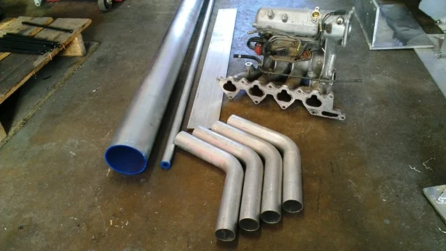
Choosing the components to build a spec manifold by hand would prove to be very tricky. I didn't want to use a lot of pre-made components like bungs, flanges, and plenums since they could easily be made. The only portion of this project I decided to settle on was the runners. While I could bend some aluminum tubing to create the correct angle, I felt it would be less of a potential performance loss if they were mandrel bent.
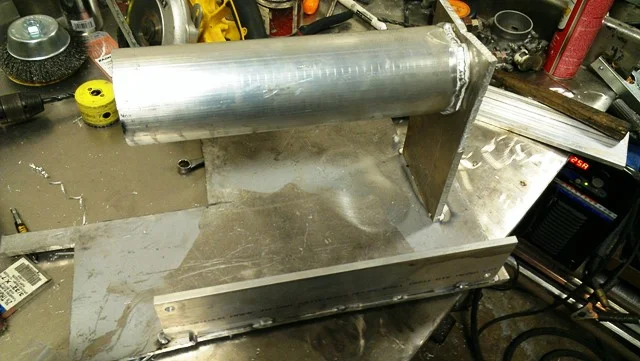
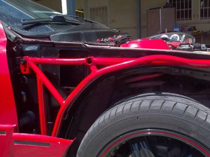
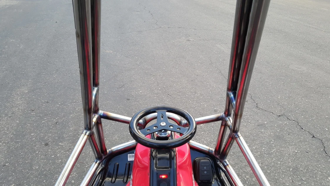
The Jig
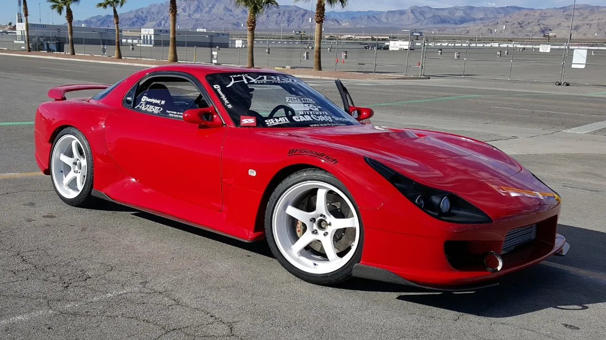
Placement of this intake manifold was determined to be at the same location as the factory manifold. This required me to build a temporary placement jig based off of the factory intake manifold.

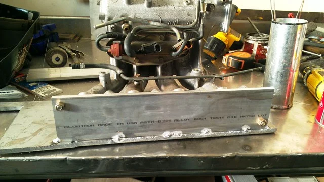

It only takes a few minutes to drill some holes and tack some plates together to make a placement jig. With everything set and ready, I started on the throttle body flange.
Throttle Body Flange
This is a very simple piece to build. Cutting a near perfect round hole is rather difficult to do by hand, so I used my hole saw attached to a cordless drill. The final bore was to be 60mm to match the throttle body. While I did not have a 60mm hole saw, I did have a close 2.25" hole saw. After making the initial cut with the hole saw, I used a flap drum on the end of my air grinder to finely bore the diameter and polish it nicely for undisturbed flow.
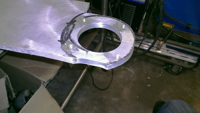


While I did use power tools to make the holes, they were completely dependent on hand movement. Any mistake made by me would destroy the piece. To really pep myself up for what was to come with the "strictly hand tools" portion of the rule, I grabbed a file to start making my notches for clearance. This was rather time consuming, but once you get into the groove, it went quickly. All of radius cuts to create the round outer shape were made using a cutoff wheel and a flap disc fitted to my grinder.
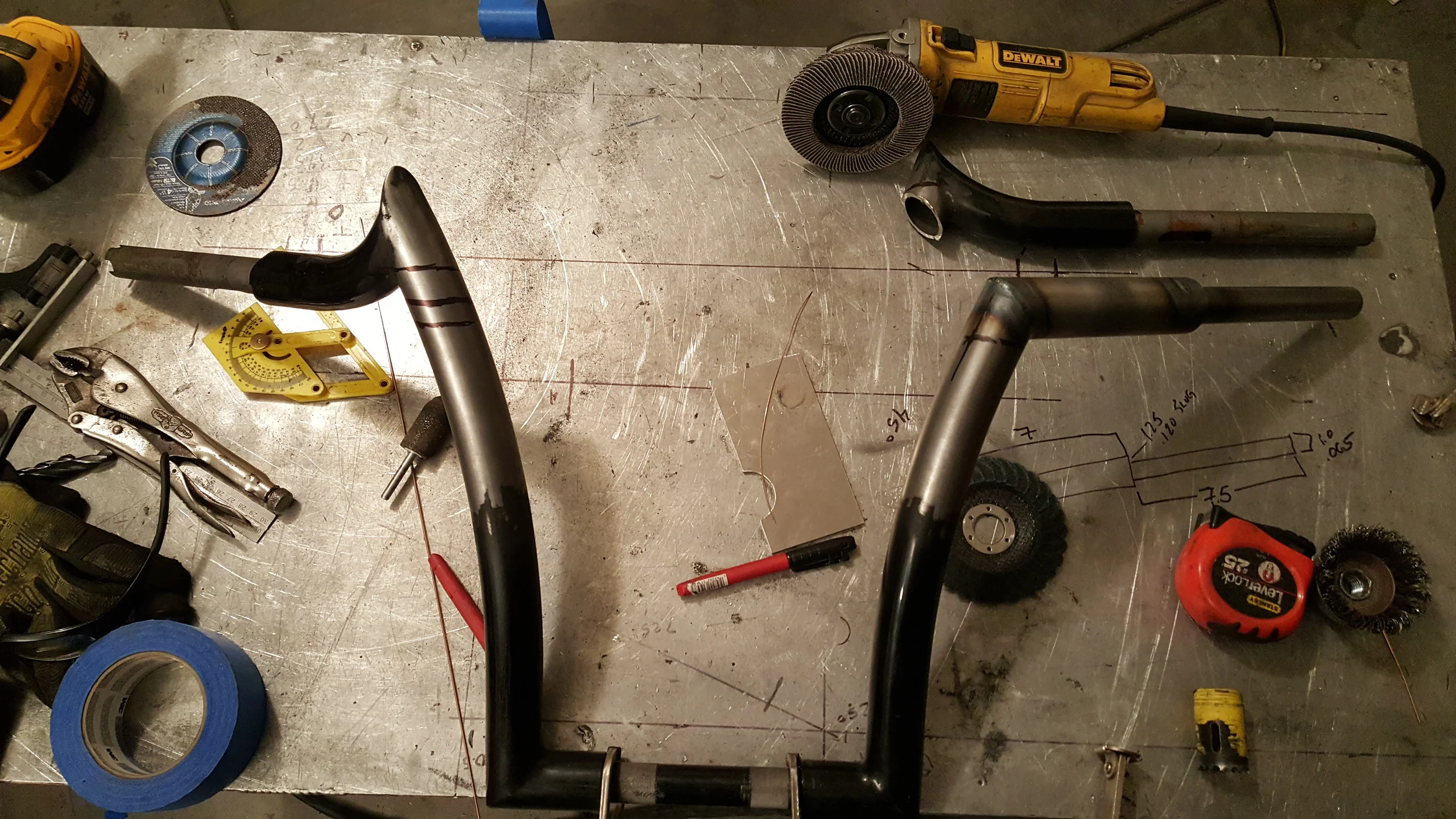
Velocity Stacks
Velocity stacks were definitely one of the more difficult items to figure out. Most velocity stacks are created on a spinning lathe, or are CNC machined from billet. So how could I possibly bang out a set of velocity stacks with only simple hand tools?
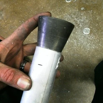
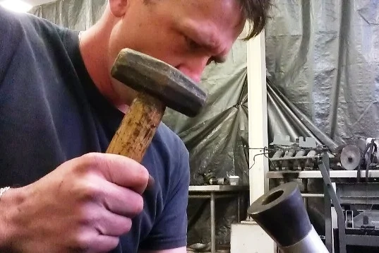
I started with a tapered cone. I was actually lucky that the cone I had (from a balancing machine) was .89 degrees under the exact taper I calculated for the velocity stack requirements of this build. That was definitely a number I could live with. If the cone was not close, I would have ordered one with the correct taper from my local machinist. After a few straight smacks with a mini sledge hammer, the taper was formed. Each tube was precision measured after the taper forming to ensure each taper was within tolerance.


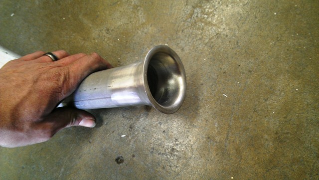
Now for the bell. I lucked out on the tapered cone, but how am I going to form the bell without a press form? I searched high and low for anything that would net me a 0.25" radius for the bell. Everything I thought of was either too flimsy, or simply didn't allow me to access it to properly form a bell mouth.
Just as I was about to give up and run to the hardware store, I looked straight down at the table and found my radius.


This is an extremely time consuming method of banging out a velocity stack bell. Too much deformation at once in a central area will cause the aluminum to tear. Too much force will cause the metal to compress and become too thin in that one section (hammer marks). Too much deviation in size will not allow smoothing and final matching of size of all 4 velocity stacks.
After the initial shaping was complete, a half round file was used to smooth out each transition. Progressively finer emery cloth would put the finish on each stack. Each velocity stack was measured and all were matched using precision measuring instruments to ensure all four were within tolerance.

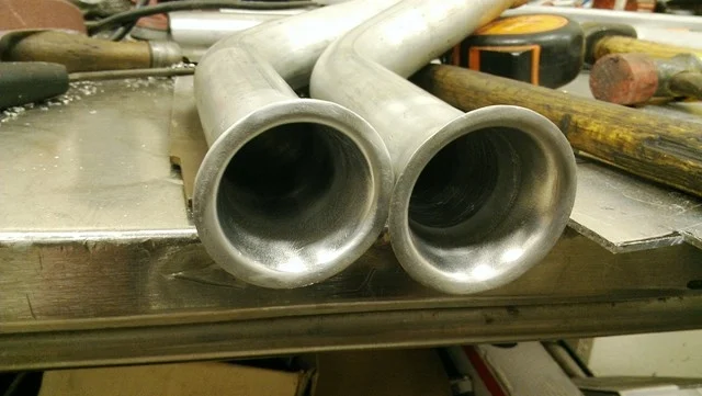
I can proudly say that absolutely ZERO machines or mechanical devices were used to create the velocity stacks. They are 100% hand made.
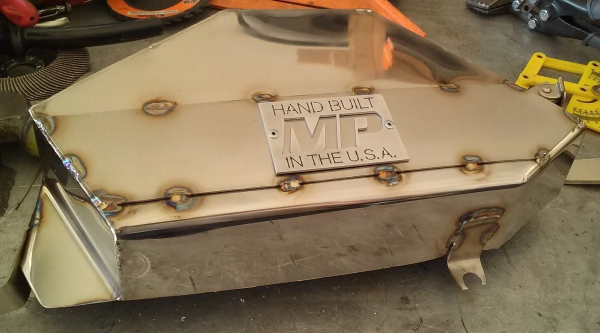
The Plenum (Part I)
Plenum size is very important to the overall performance of an intake manifold. Too large of a plenum and you will run into less throttle control as well as vacuum related troubles. On the other end, if your plenum is too small, you will simply not gain, or even lose power. This plenum had a particular amount of volume requirement which started out as a 4 inch round tube which will eventually cut down to volume. The initial cut was to length.

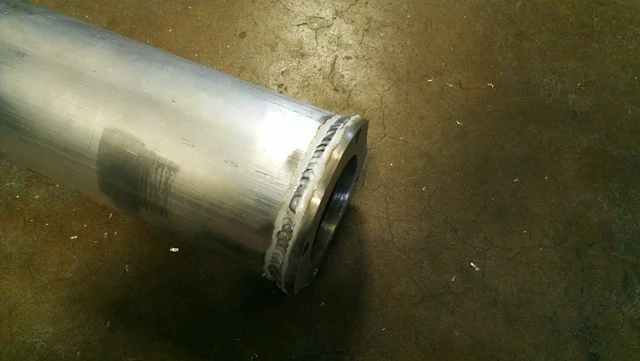

It only took a few minutes to prep the tube for welding before buzzing the flange on. A mock-up throttle body was used to check the fit and notching of the throttle body plate and plenum clearance. Some lite metal work needed to be done to the plenum in order to mate to the notched sections. Once the full plenum was welded in, the plenum was tossed into the jig.
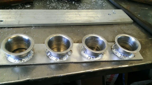
Adding the velocity stacks straight to the plenum would be ideal for ease of install at this point, but the volume of the plenum, even with the stacks in it, is still too much. The driver would have less throttle control but a great WOT experience. The volume of the plenum needs to be reduced to the correct calculated volume without reducing the flow to the velocity stacks. The best way to reduce the plenum volume without reducing potential flow is to weld the velocity stacks to a plate.
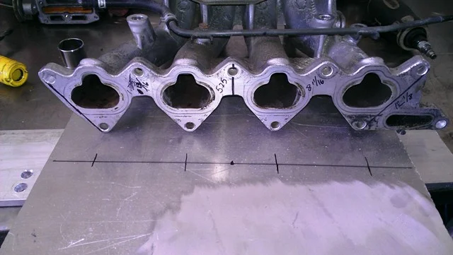

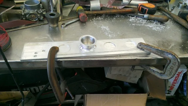

Correct spacing of the velocity stacks was achieved by thoroughly measuring the intake manifold ports at the head flange. Those measurements were translated on to a piece of 6061 where the hole saw was used to cut out the ports for the velocity stacks to be welded to.
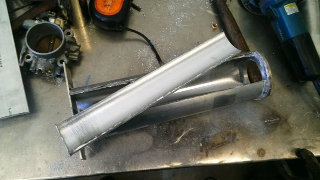
While the velocity stacks cooled down, I moved on to the plenum. A section had to be removed to make room for the velocity stacks. This also reduces the volume over all. After some careful measurements in the jig, and a few minutes to double check the angles of the runners, the grinder came out to slice it up. In order to prevent spreading of the cut round aluminum, a piece of scrap was welded to the rear to hold the roundness.


Complete hand fabrication has proven to be challenging, but is the hard part over with yet? Find out in part two where I have to figure out how to cut an oval hole and injector bungs without machines.
Be sure to like, follow, and subscribe to all the social media pages for the latest updates!
Help fund future episodes of The Fabricator Series with your Donation and receive exclusive SnapChat access! Even the smallest donations go a long way.
So what do you think? Have any questions?
Tell me about it in the comments below of email The Fabricator.
Likes, comments, and shares appreciated by all!


Purge Blocks actually serve more than one purpose. Do you know what they do?