You would think after the few snags from earlier out of the way that I had everything all taken care of. Well, sadly, the problems had only just begun. What almost ended this build for a "full cage" instead of a roll bar like I tried to talk my way into? Here's how everything went down.
To better explain the problem I had, let's look at the drawings. You can scroll through each manually, or wait for each to auto scroll.
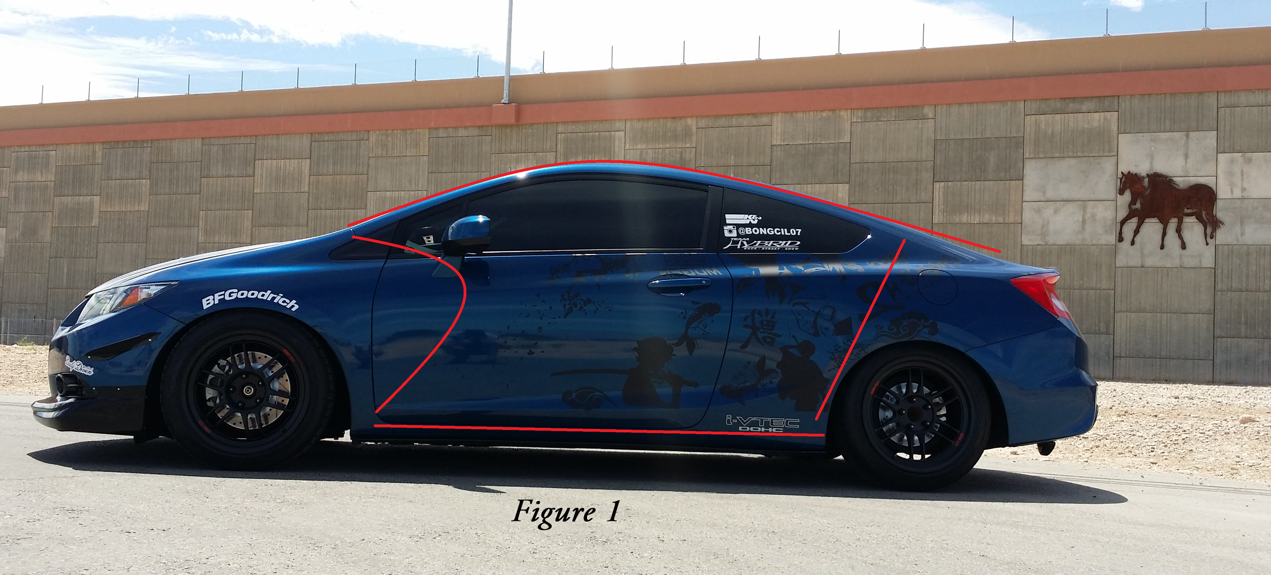
Figures 1 & 2
The is the basic design of the space I had to work with. You can see the design both on and off the car for reference. The red lines outline the roof, dash, floor, and rear. While most of this may appear to be pretty text book of a car's interior, it is actually the basic outline of the problem.
Remember those "nice swooping lines and low roofs" I mentioned in Part 1? This is exactly where I ran into the design issues. It is because of the large radius curvature of the roof that I almost abandoned the full cage concept all together.
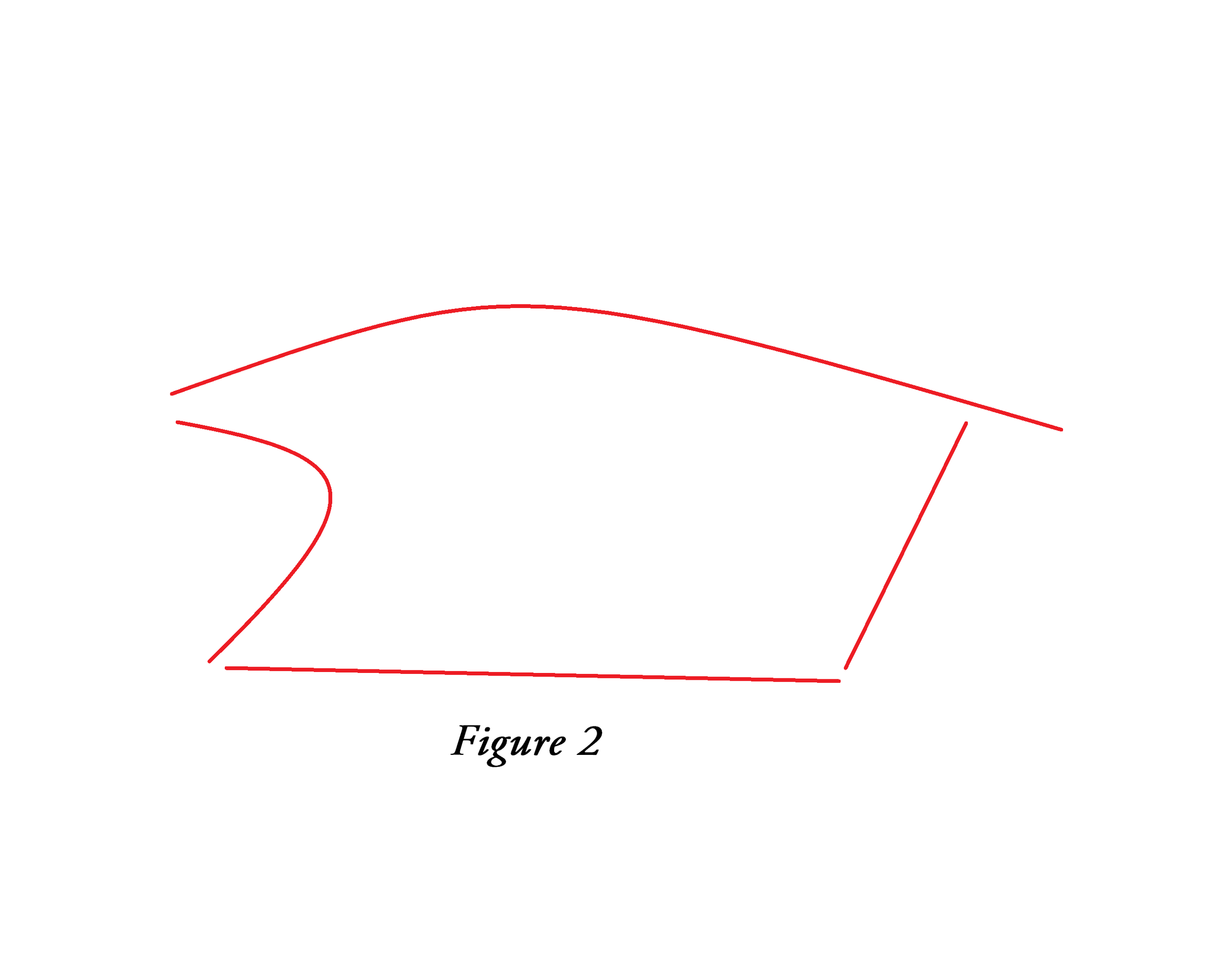
Figures 3 & 4
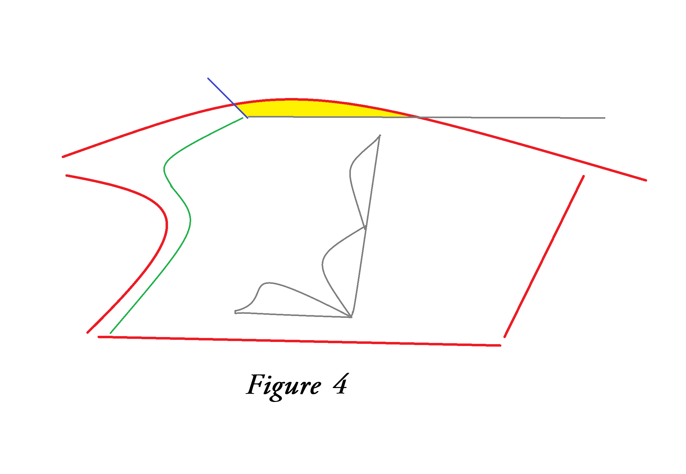
Taking a look at the driver position vs the outline of the cabin area, the blue arrow represents the top of the roof radius and the gray arrow represents the Line Of Sight (LOS) of our measured driver (the owner). These two measurements are ones I have to keep in mind while designing a cage.
There are two types of designs typically used in roll cage design when referencing the tubes used forward of the main hoop. The design I typically use sends two separate tubes stretching from the main hoop, down the A pillars, and ending at the floor. Connecting both left and right tubes is is the "windshield bar" which is usually bent out of the way of the driver's LOS.
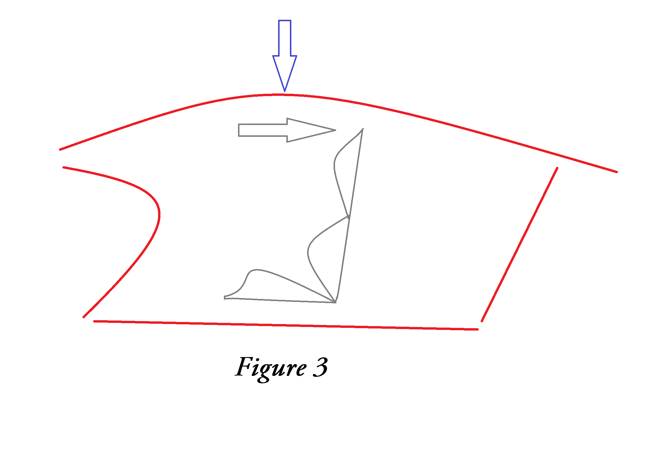
Figure 4 shows the area in yellow that is problematic for this particular portion. I do not own a bending die that will create such a large radius to follow the roof line as specified in the rules. With the gray line translated into the work area, and the blue line translated to represent the roof line, I can apply the design of the A pillar bar shown in green. The A pillar bar is a "locked in" design that I can not change because it would hinder emergency egress and LOS of the driver when looking out either window.
In order to mate the A pillar section to the main hoop section, 3 additional bends would need to be added in the yellow area in order to clear LOS, head space, and not hinder emergency egress. The maximum allowable number of bends on an A pillar tube is 4 bends.
I decided to have a go at it anyway. This was a tricky section, but I was determined to get it. I simply couldn't think of any other way to route and bend tubing to meet all the requirements of this cage. I found a few "lines" in the interior to route the tubing around and I figured this would be tough, but I'd get it.
The problem ended up being very simple. No matter which angle I ran the tubing at, there was always a problem with the tubing interfering with LOS, egress, or the driver in general (like ending right through the drivers head position). There simply was no way to bend this tube to match all the requirements. After bending and scrapping an additional 18 feet of tubing, I threw in the towel. I have wasted almost 40 feet of DOM tubing and there was no way to get this A pillar tube bent. It was time to call the owner.
As always, the owner was very quick to arrive with his typical enthusiasm about seeing the latest updates, but this time the enthusiasm was gone. We discussed a few options and changes with possible alternative designs, but at the end of the day, there was no way to create this portion which will ensure every portion of the requirements are met, and I will not build a "show cage" which may sacrifice safety. The only solution was to swallow my pride and knock this whole build down to just a roll bar which had already been built and installed.
I couldn't believe I just suggested that. While the owner was off making the call to the sponsor with the latest news of the build, I stared intently at the car. I simply couldn't believe I allowed a car to get the best of my abilities. This has never happened before and I simply couldn't let it go. There was a bit of gloom in the air for a little bit and of course I kept hearing in my head; "the sponsor specifically stated Full Cage."
Then it hit me.....

There are two additional designs permitted in roll cage design. Even though I very rarely ever use these additional design options, they are still allowed, and I realized I did not even bother to factor them into a probable design for this build.
The first design is often called a "front hoop". This design is much like a main hoop, but is routed up the A pillar, across the windshield, and down the other side in one continuous piece. While this is very practical and possible on this build, the radius of the bends from the A pillar to the windshield line would cut off about 30% of the driver's LOS. The design was soon scratched.
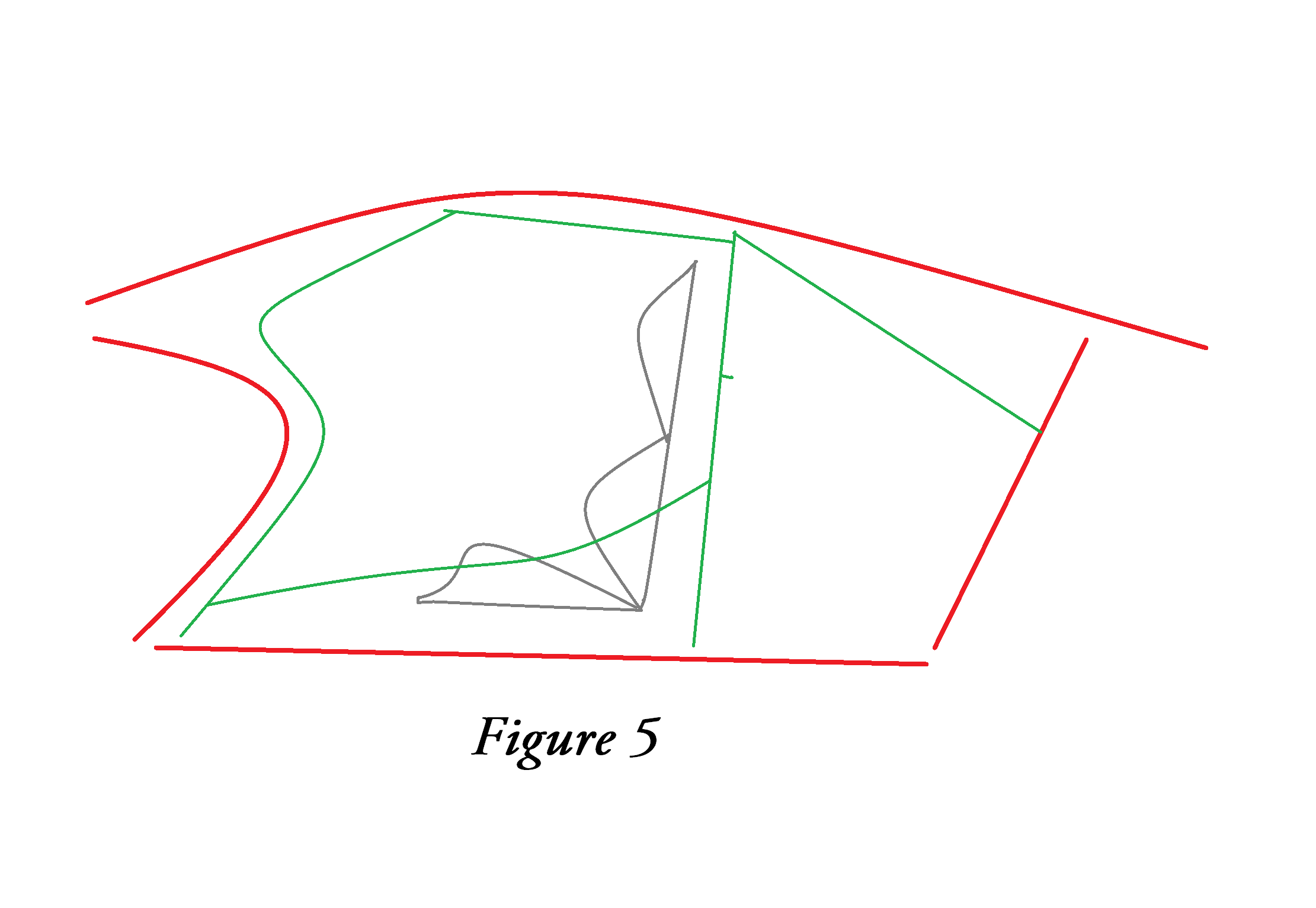
The last and final design was the "Halo" configuration. This is one continuous piece that start at the main hoop, follows along the windshield line, and ends back at the main hoop on the other side. After a few very careful measurements, I knew I had found the solution. I frantically called the owner and proudly said "I've got it! Forget about what I said earlier today. I'm going to make it happen."
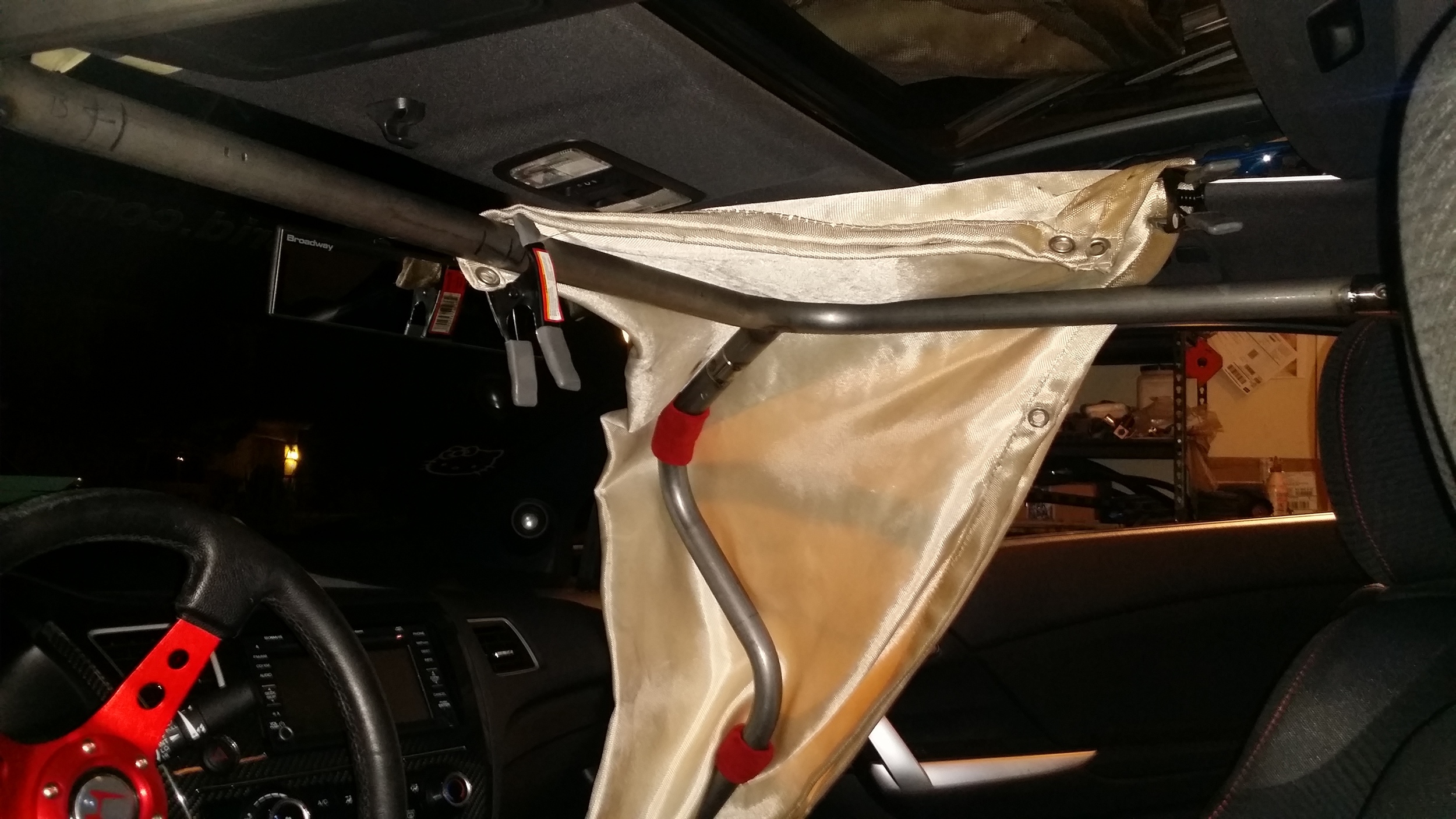
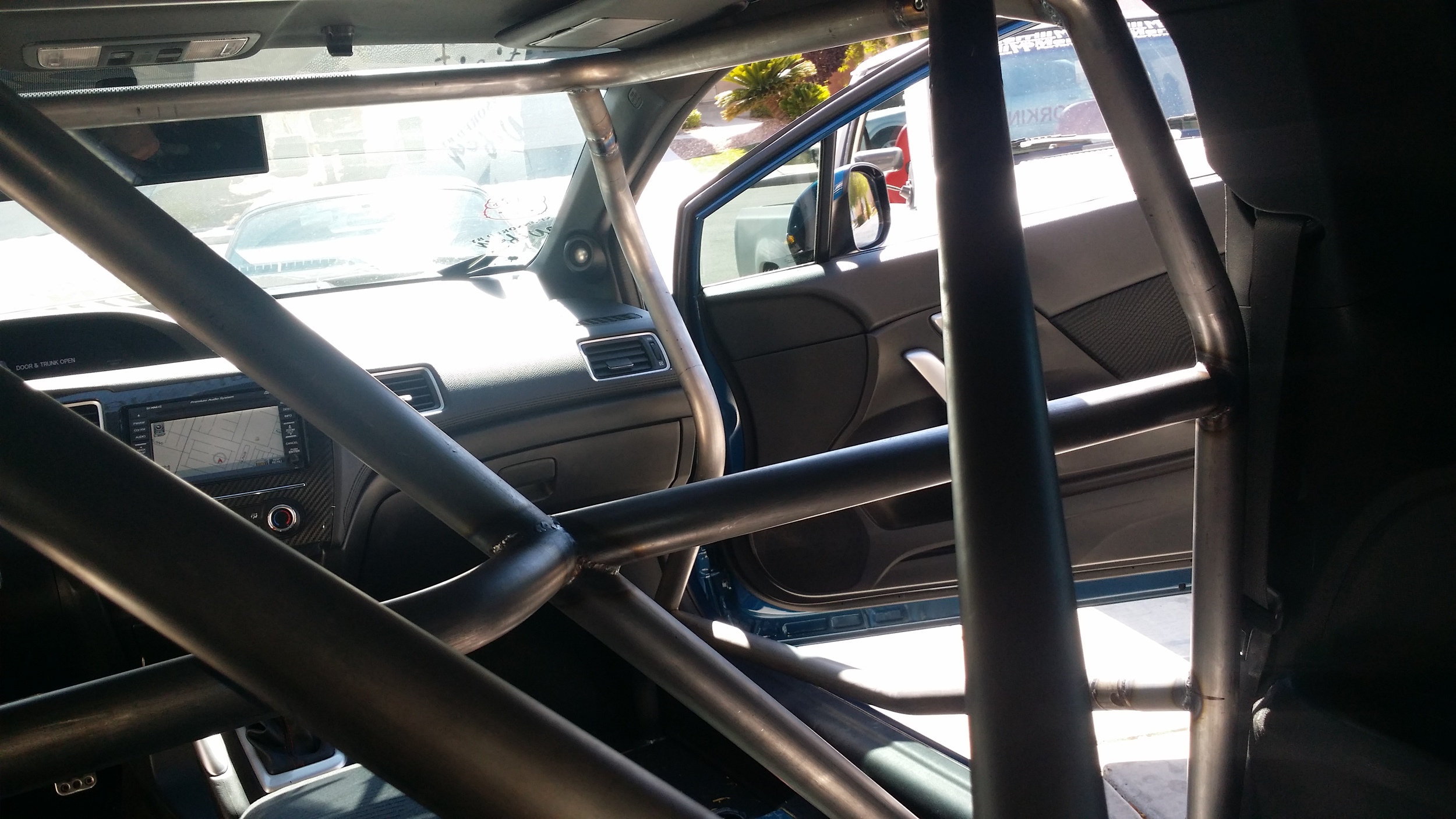
The halo design allows me to closely hug the roof while placing it at an upward angle (shown in Figures 5 &6) that will clear LOS while keeping the A pillar bars in their position. The only sacrifice is the "Oh S**T!" handles which needed to be removed. The build was back on!
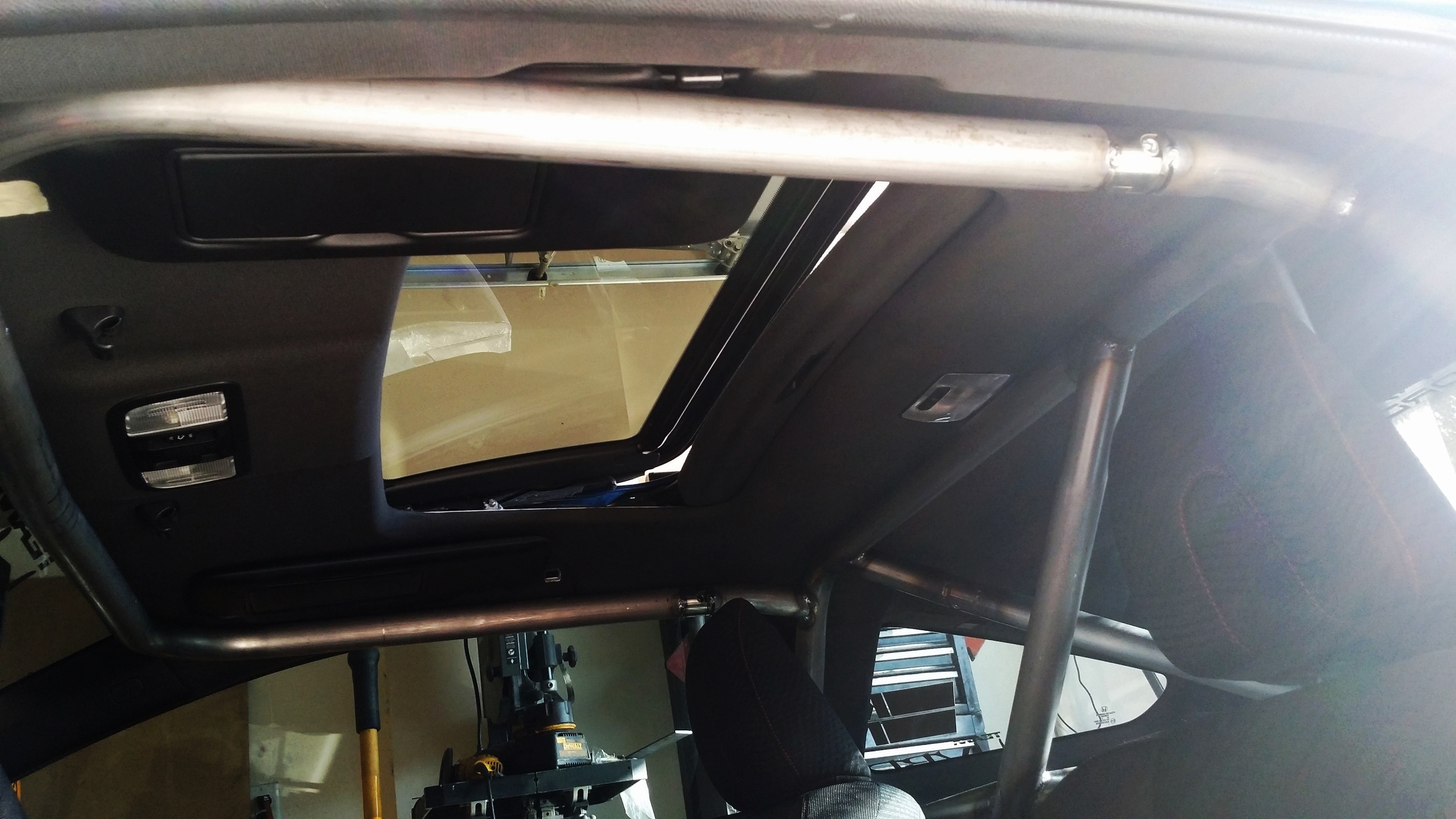
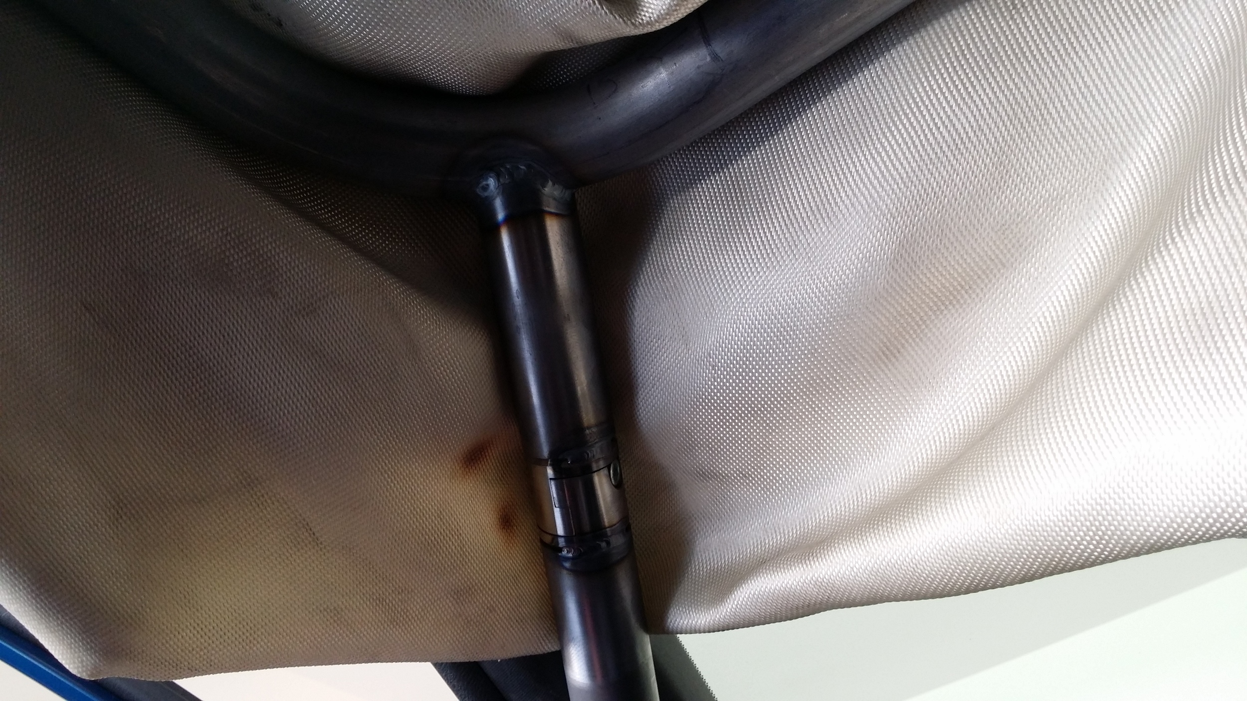
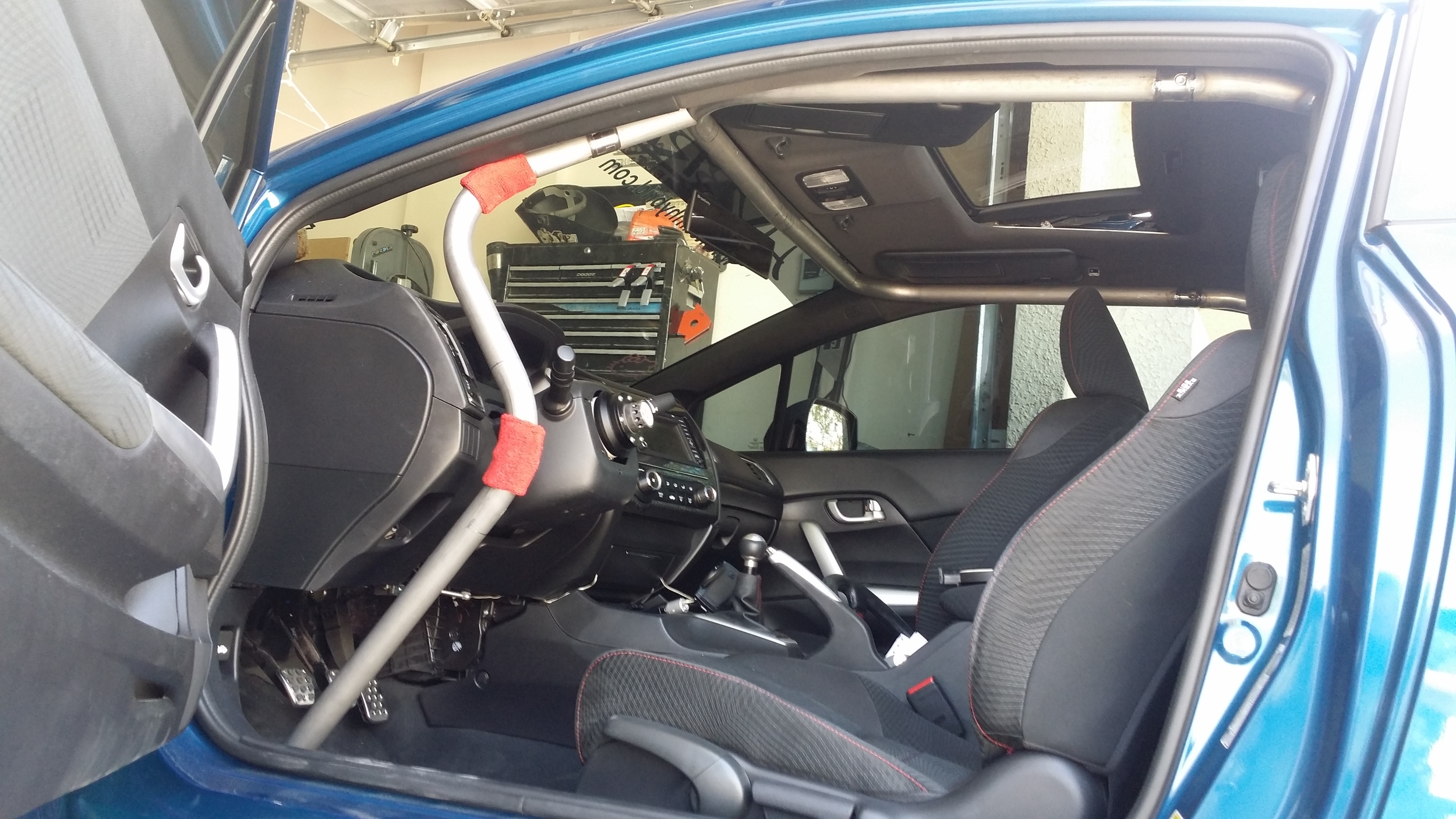
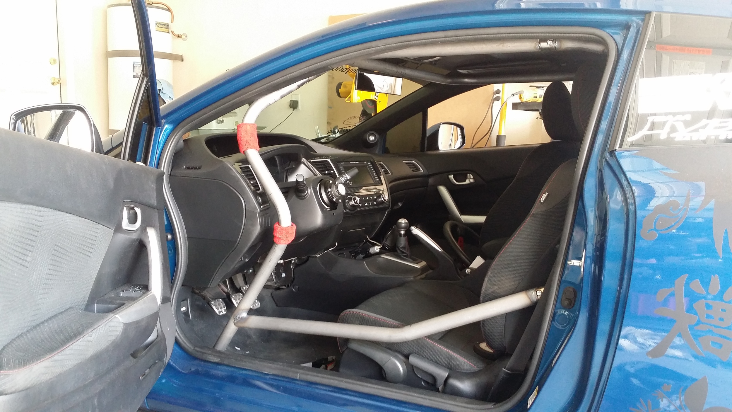
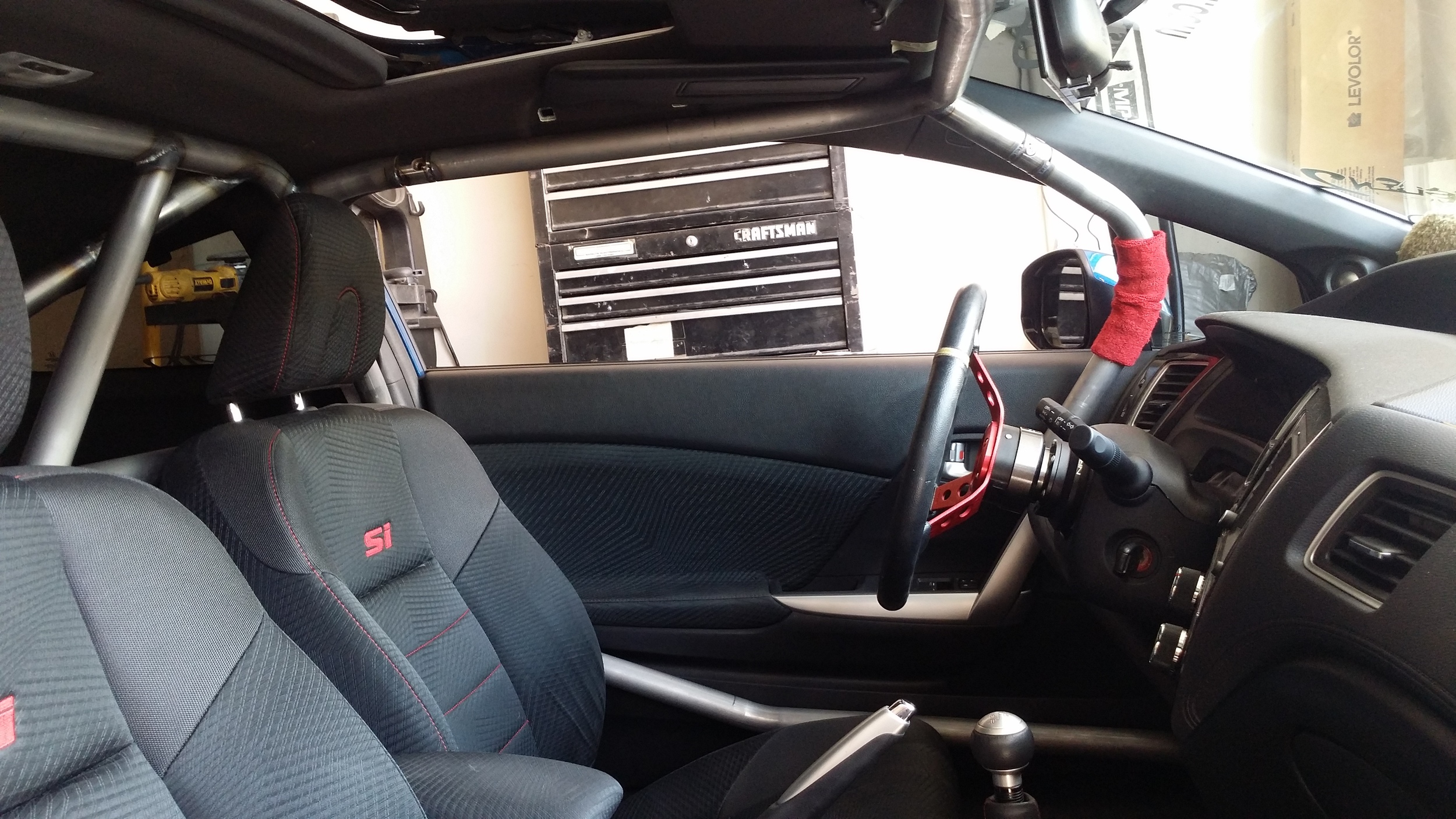
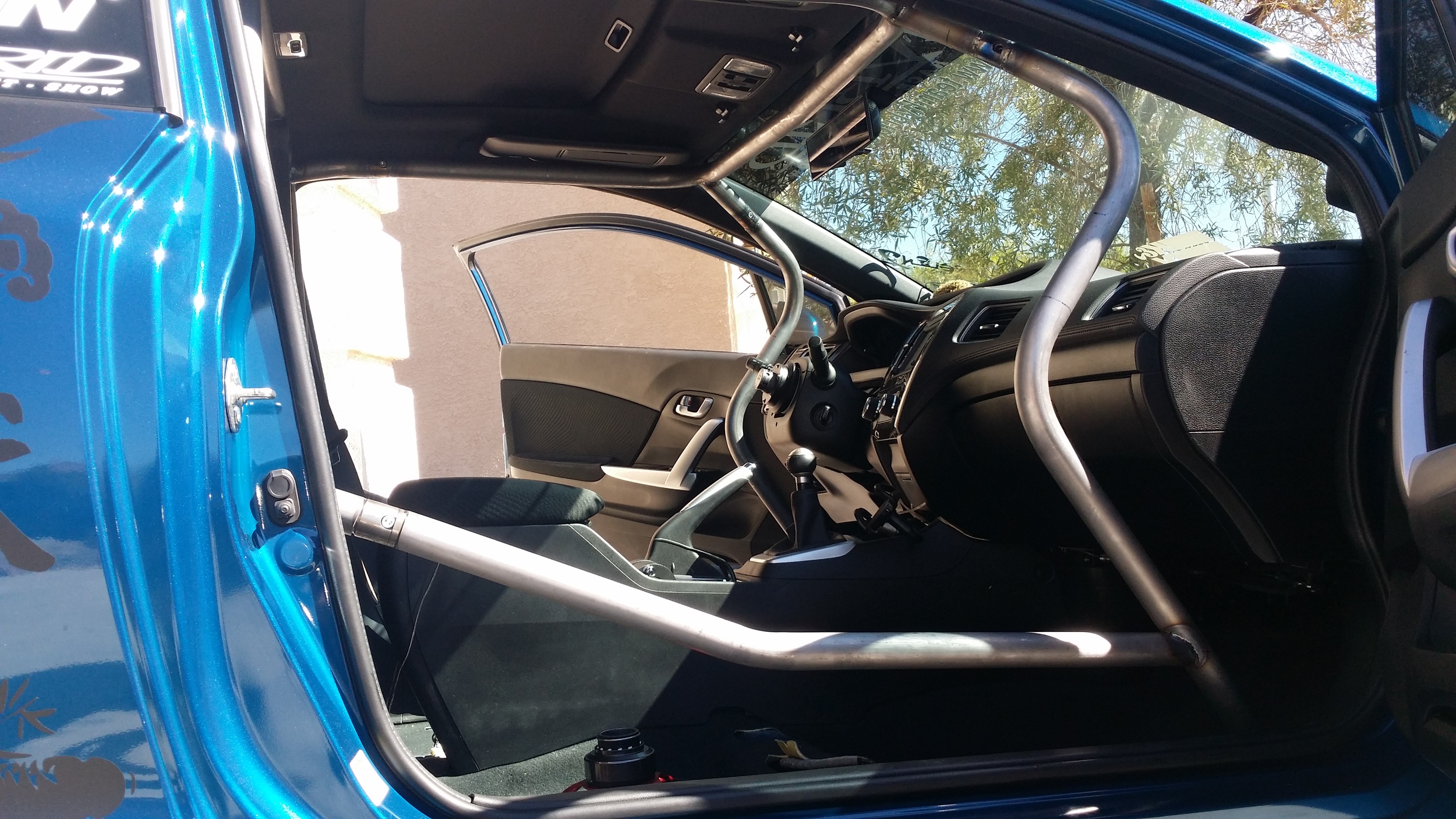
I wasted absolutely no time bending up the halo hoop. It was a little tricky to manage because I haven't utilized the halo design in years, but it came together within a couple hours. Once I decided on the mounting location for the chromoly tube clamps, I welded everything in place. Next I immediately started on the A pillar bars. These definitely presented a challenge because of the dash design along with the angle of the A pillar. It took about an hour to confirm the fitment would not interfere with any handles, buttons, LOS, egress, or driver position.
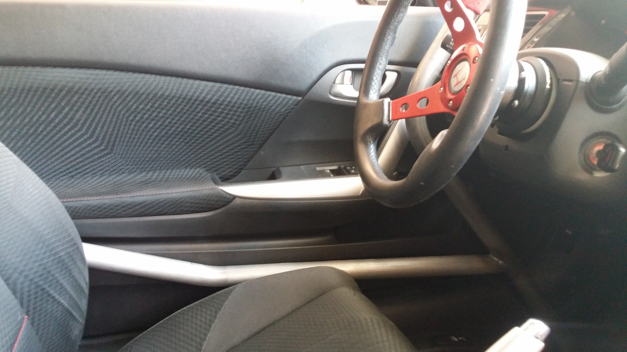
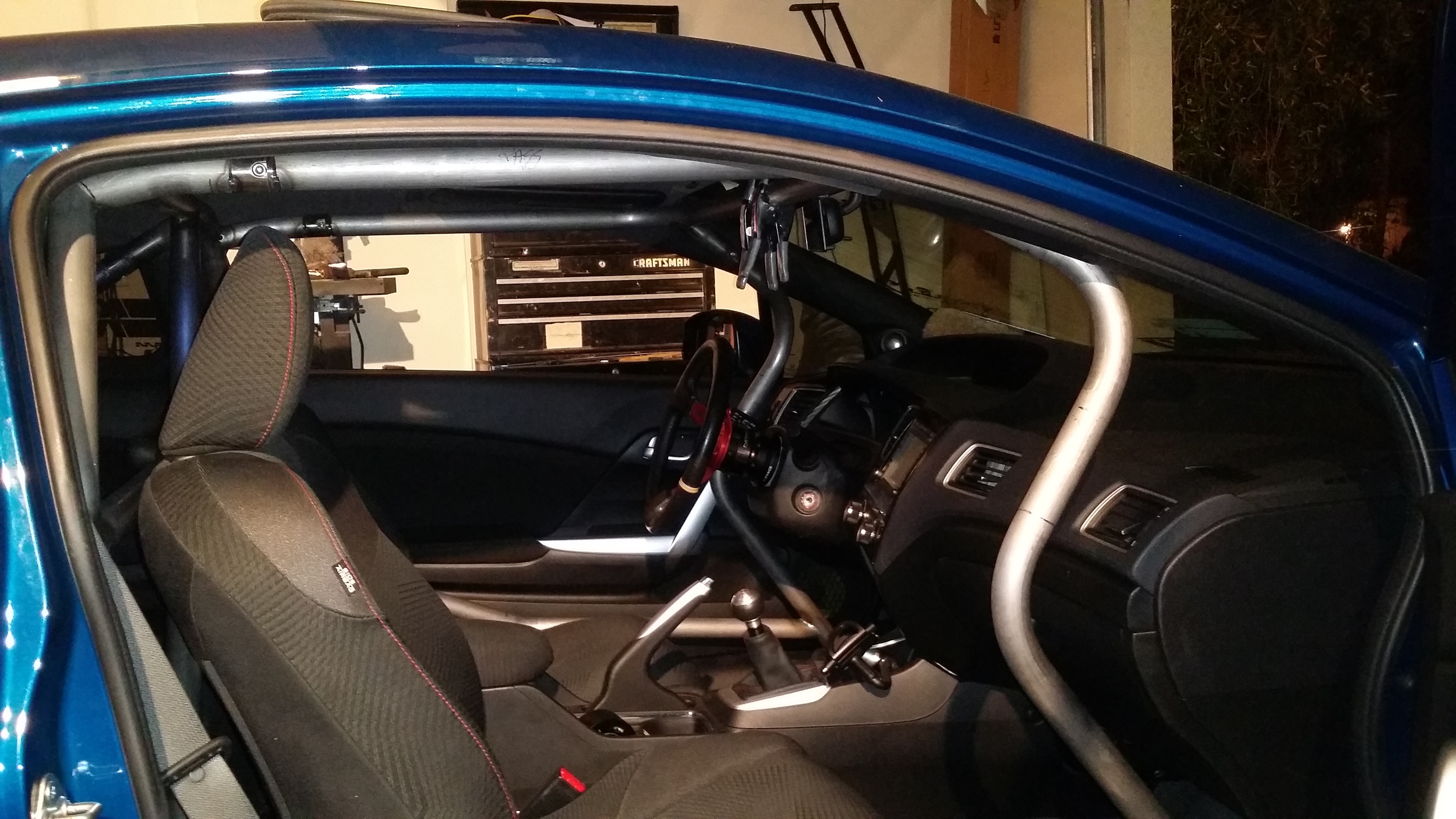
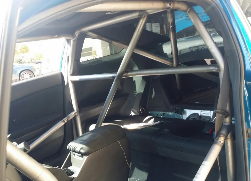
Once the position was set for clearance, another chromoly tube clamp was added followed by the welds to keep it all in place. After a brief cool down period, a fit and function test was performed to ensure that everything could be accessed and no interference was created after the tube cooled. One more fit check was required with the driver, so I called him back over for measurements and door bar placement. It took little time to confirm the door bar placement and get it installed with another tube clamp.
Now all that was left was to knock out the work on the passenger side and pull it for final welding and coating. The one part of the passenger side that presented the most challenge was the glove box. There is no room to open it all the way with a tube blocking it. Luckily the dash is not symmetrical on both sides. The passenger side is set a little more forward than the driver side which allowed a little bit more space to allow enough opening to access documents and other glove box essentials.
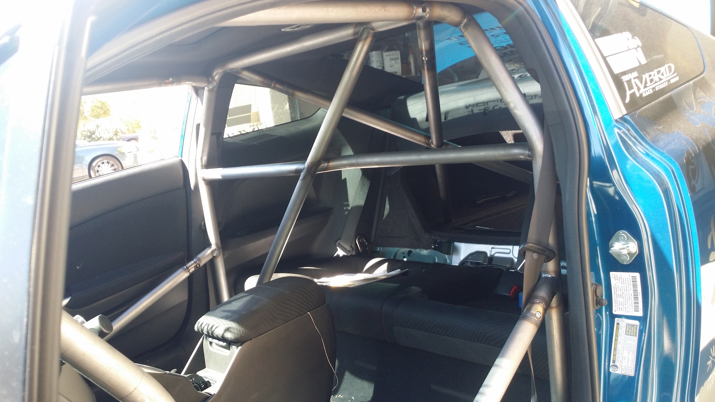
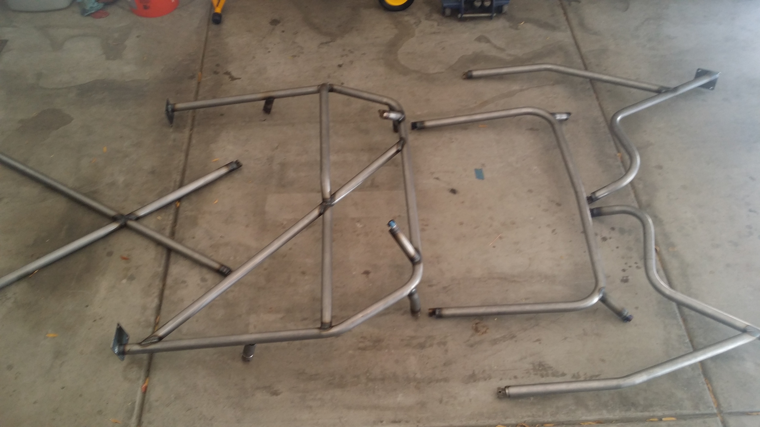
Seeing this full cage out of car, all welded up, and ready for coating is the biggest relief and feel of accomplishment. Not only did I tell defeat to "shove it!", I made my client and his sponsor happy. What could possibly sweeten this build up to make it any better?
I'll show you in Part 3!


You have seen the craziness of Parts 1 & 2. Now see what was added that has never been seen on this chassis EVER!