TIG Cups and How to Set Them Up Properly

No. You don’t need a giant set of cups in all different sizes. You could actually use just one cup for everything.

Seriously.

Key Takeaways

If you haven’t figured it out by now, we prefer a no BS approach to welding. We like to keep it as simple as possible. You really don’t need a bunch of different cups for every TIG job you encounter. In fact, you probably don’t even need half of the cups you think you do.

The purpose of a TIG cup is to direct shielding gas to the part you are welding. Literally - that’s all they do. So why are there so many different sizes? Procedures.

But if you’re not following a written procedure - you can follow a very simple set of rules for every cup! We will get into which cup is used for different metals in a moment, but first, let’s uncover those rules.

  • Each cup is referenced by a number

  • The number is the diameter of the outlet measured in 1/16 inch increments

  • That measurement also corresponds to tungsten stick-out length

It’s a good idea to follow the tungsten stick-out rule closely. Not only does this ensure the shielding provided by the cup is adequate, but it also means you are not cutting off gas flow to your part. It also means you aren’t operating it with too much which can cause more coverage issues, blowouts and more.

  • The stick-out rule is a “window”

  • You can stick out a little more or a little less as long as the gas flow is set correctly.

The number of the cup also tells you where to set the gas flow at. If you gas flow is not set properly, you are going to encounter problems… lots of problems. Too little gas flow can cause the weld to overheat and show unsightly oxidation. Too much gas flow is actually really bad as it can stir the atmosphere into the shielding zone which is just like having no gas at all. It’s also extremely wasteful.

Gas Flow Formula (CFH)

  • Cup Number X 2 = Minimum Gas flow in CFH

  • Cup number X 2.5 = Maximum Gas Flow in CFH

  • Gas flow is measured at the center of the ball on a standard flow meter

Gas Flow Formula (Lpm)

  • Cup Number = Minimum Gas Flow in Lpm

  • Cup number + 2 = Maximum Gas Flow in Lpm

  • Gas flow is measured at the center of the ball on a standard flow meter

DO NOT SET GAS FLOW HIGHER OR LOWER THAN WHAT IS RECOMMENDED.

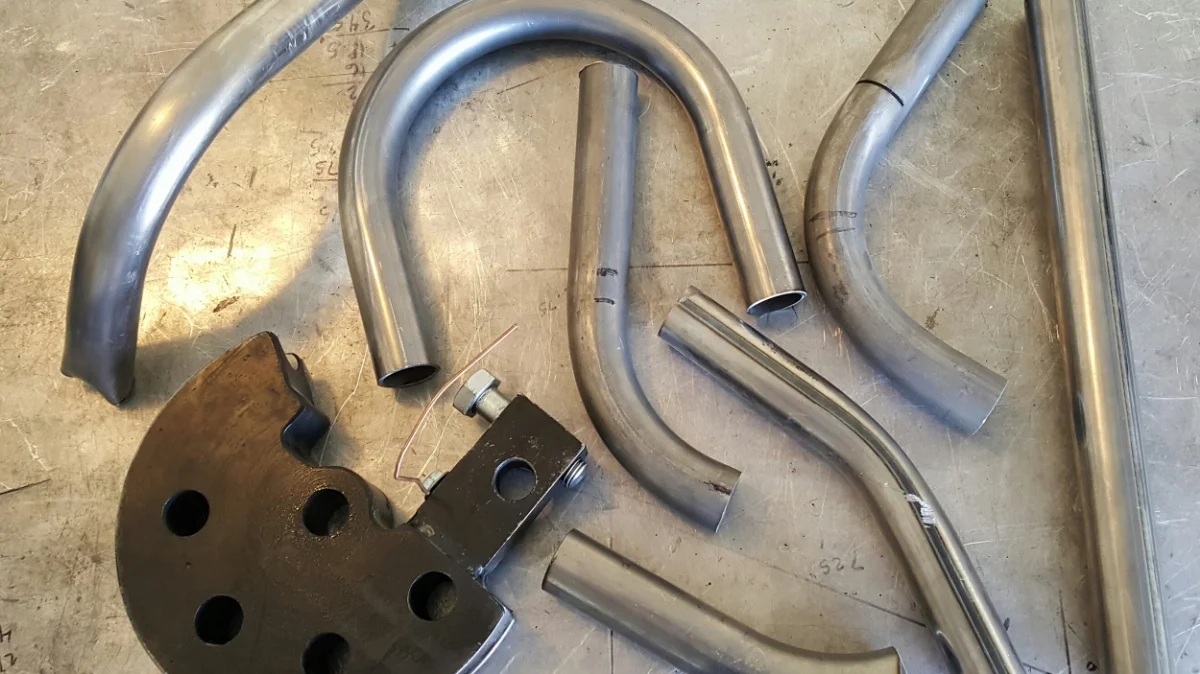
So which cup should you use and why? Believe it or not, Justin only uses 3 cups for every single metal he welds from aluminum to Titanium and more - 5, 12 and 16.

Pick the correct cup for TIG welding
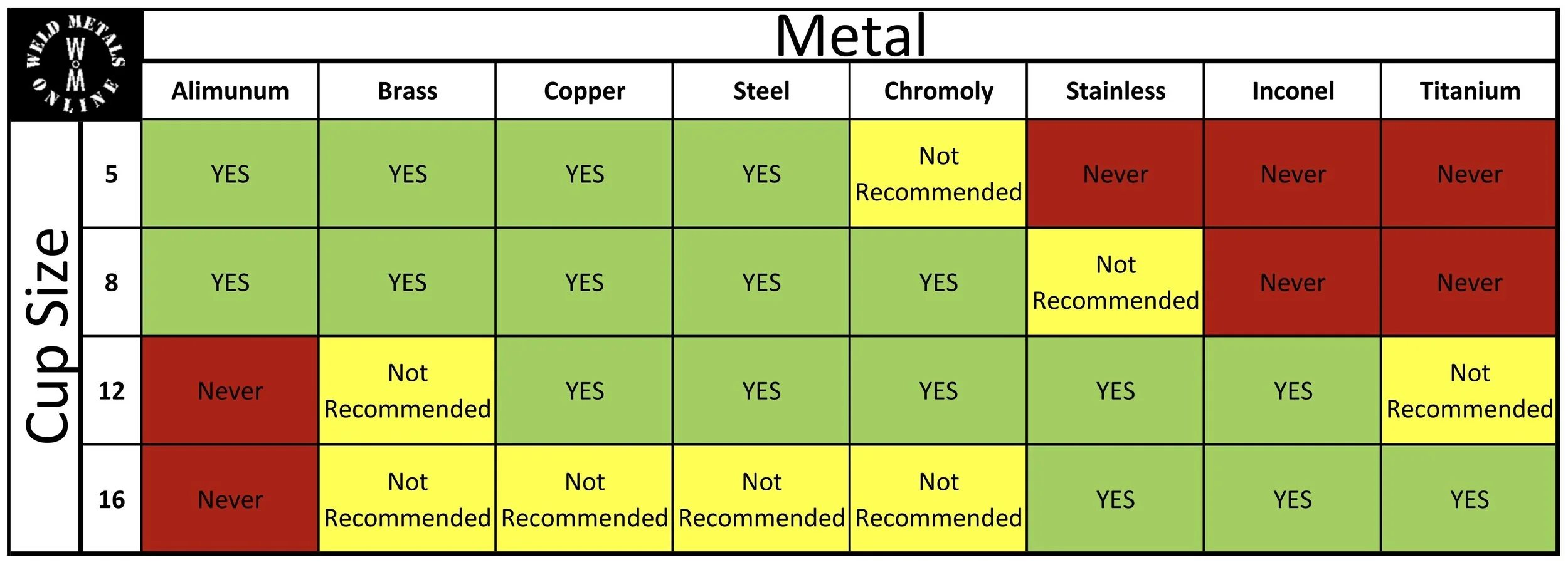
  • 5# standard or gas lens cup for aluminum. The smaller diameter means more control and less etching on aluminum. It also uses less gas which aluminum does not need a lot of

  • 8# gas lens cup is a great all purpose cup which can be used on aluminum, steel and even stainless if you’re good at it

  • 12# gas lens cup is great for decorative welds and rainbow pattern making. If you can afford the argon, a 12 is a great general purpose cup. NEVER use it on aluminum

  • 16# gas lens cup is for the exotics like titanium. It’s also great for stainless if the goal is to keep most or all of the color out of it.

Cheap consumables produce cheap results. This includes cups and bargain kits with a bunch of different sizes and types. The classic waste of money almost everyone eventually realizes is the full set of Pyrex cups on Amazon with the infamous green o-rings and crappy gas lenses that fall apart. Trust us when we say - they suck.

Quality products come from major brand names (not bargain names). If you find it on Amazon competing with something that looks just like it - guaranteed it’s cheap. But there are a few rules you can follow when it comes to buying quality consumables.

  • Premium Brands: CK Worldwide, Furick, Edge, etc.

  • OEM Brands: Miller, Lincoln, Esab, Primeweld, etc.

  • House Brands (welding supply store): Radnor, Prostar, etc.

Go ahead and buy the big fancy kit. You’ll eventually discover that the only difference between a No. 8 cup and a No. 7 cup is...

One.
— Justin

This article is proudly written with 0.00% AI.

Tungsten - Just Pick a Color Already!

It doesn’t matter which color you choose to TIG weld with. They all do the same thing.

…Kind of.

Key Takeaways

There are many colors of tungsten to choose from and many of those colors used to mean something. But on modern inverter machines, the rules don’t necessarily apply.

Most tungsten color charts reference a rule that was written decades ago for old transformer machines. Some color charts don’t even show modern rare earth blends because of brand conflict. But the good news is we can sort it all out.

When TIG welding was created, we didn’t even have a tungsten color. We just had tungsten. Pure tungsten is now color coded green, but before it was green, it was just tungsten that we used to TIG weld. It did the job, but over the course of time, it would fall apart and require a lot of time consuming maintenance to keep welding.

  • Green (pure) tungsten was the original tungsten

  • Green tends to dull out, split, and requires having many sizes for different amperage ranges

Blending oxides into pure tungsten solved problems. Early transformer machines were basically all the exact same machine with all the exact same issues. Over the course of time, it was discovered that blending different oxides would solve some of those problems.

  • White tungsten (zirconium oxide) provided better arc starts on AC and could handle higher amps than pure (green) which means you didn’t have to switch out for a larger diameter

  • Gray tungsten (cerium oxide) was the first all purpose tungsten that was remarkably stable at low amperage

  • Gold & Blue tungsten (lanthanum oxide) became very popular as gold was very stable at low amp DC welding, and blue was good for almost everything and became the all purpose super tungsten

  • Red tungsten (thorium oxide) was considered virtually indestructible as it was stable and strong on every end. It could be used on both DC and AC, but it was most commonly used on DC only because it would kind of fight back on AC since old machines were very primitive.

But wait - there’s even more colors. Black, yellow, and brown are not included on the list because they have likely been phased out or not used as often. Additionally, some colors have changed over time. Ceriated tungsten used to be color coded orange until they changed it to gray.

The radioactive red scare was a real thing. Sometime around 2011, it was discovered that thorium oxide in red tungsten is potentially dangerous as the dust emits particles of radiation which is really bad for you if inhaled. As a result of this finding, many packages were pulled from shelves until years later when they basically found out it’s not as bad as they originally made it out to be. Basically, if you’re using red tungsten, don’t sniff the the grinding dust off the table.

But the damage had been done for most people at the time and many people were forced to consider using a different color. That’s when the rare earth blends came into play.

Rare earth blends feature several oxides to make one super tungsten. With the radiation scare an the air, manufacturers were at a race to create the next best alternative to red tungsten which was just as indestructible (if not better) but without the radiation part of it.

This is when we got more colors and blends from different manufacturers.

  • Purple, pink, chartreuse, teal, and a few other color codes feature several oxide blends of create long lasting and strong electrodes

  • Rare earth blends weld every metal on every machine ever made

Many websites do not include these other colors on their tungsten charts. The primary reason is because many of the brands conflict. Since rare earth blends are left up to the manufacturer to define and color code, they are often marketed to compete with other brands that basically do the same thing.

In other words, CK Worldwide is not going to put E3 (purple) tungsten on their chart when they manufacture and sell LaYZr (chartreuse) tungsten as their own rare earth blend. Blue Demon is not going to advertise teal from DGP when they sell pink as their color code.

So which color should you use? It doesn’t matter… unless you don’t follow the rules.

  • Old school transformer units should stick to the classic color chart if rare earth blends aren’t suitable (for whatever old headed reason)

  • Inverter machines should NEVER use green (pure) or white (zirconiated) tungsten as they have a arc start and stability problem.

The best tungsten will NEVER be agreed upon. It is entirely up to the user of the tungsten to determine what is “best” for their application. You will often find a lot of stubborn people that will never change their ways. You will also find a lot of people that bandwagon tungsten colors like a sports team (blue is extremely popular). Some people are literally afraid to change their mind or opinion, or even try something new even if nobody knows they did. It literally is that silly.

In my experience of trying several colors more than once over more than 20 years (of course this is how everyone qualifies their remarks), I recommend CK Worldwide LaYZR tungsten. At the time of writing this, I think it is the best and you can literally use just one size for almost anything.

  • LaYZr welds EVERY metal on EVERY machine EVER MADE in the history of EVER

  • LaYZr in 3/32” (2.4mm) size is stable enough to weld razor blades, but strong enough to weld 1/4” (6mm) aluminum with the same piece

  • LaYZr holds its point over the widest amperage range without dulling in the higher end

  • LaYZr color code is chartreuse (NOT green) and is often asked for by name

Bottom line - run whatever color you want. It really doesn’t matter which one anybody thinks is best. It matters what YOU think is best.

Just pick a color. If you like it - run with it. If you don’t like it - pick another color. Just don’t get stuck thinking there is only one color and nothing will ever be better.
— Justin

This article is proudly written with 0.00% AI.

Secrets of a TIG Foot Pedal that Everyone Should Know

Imagine driving down the road in your car while staring at your feet instead of the road.

Sounds stupid, right?

Key Takeaways

The foot pedal on a TIG welder is the COMPLETE control of the machine. It also serves as the ON/OFF switch of the arc. There is a lot more to it than most people realize. When people ask to see Justin’s foot pedal in a video, or during a class, the response is usually met with the question - “Do you stare at your feet while driving?”

  • We don’t stare at our foot pedal when welding

  • Foot pedal control should be intuitive just like driving a car

The answer to what you need to do is ALWAYS right in front of you. If you are mid weld and you see that your weld pool is getting out of control, you should make the correction right then and there. If you are looking at something else, you will never see the weld to correct it.

There are TWO ways to correct a weld. The first is the most common way which is by adjusting amps with your foot pedal. If you see the weld pool is too wide and gooey, or much larger than it needs to be, back off the foot pedal (amps) until it looks correct - then proceed. The second option for control is to adjust your speed. You can run faster or slower to control your bead, but this takes a lot of skill which comes over the course of time. If you can’t keep up the speed to control it, your only option is to reduce amps.

  • The weld tells you everything about what you are doing and need to do

  • Your eyes are connected to your foot which controls the pedal

  • You can either adjust amps with your pedal, or adjust speed. Adjusting speed has limitations and requires more developed skill

ON, OFF, and in between. Aside from starting and terminating the arc, the foot pedal serves as an adjustment to how much power you need to make your bead. You should learn to work the foot pedal by initially stepping on it lightly until the arc starts. Once the arc is lit, gradually increase the amps by slowly stepping on it more. If you see that you have too much power, gradually reduce the amps by slowly letting your foot off. This fine adjustment can happen hundreds of times during a weld.

  • NEVER go full throttle instantly by stomping the pedal to the floor

  • ALWAYS start softly and ramp up slowly and naturally

  • Adjust the pedal softly and naturally based on what you see in front of you

Correction is key to consistency. As mentioned, welding is all about actively making correction as you are welding. Every single drop of filler is added AFTER the question is asked: “Does this weld pool look correct”?

  • If the answer is YES - add filler, move forward, ask again.

  • If the answer is YES again - add filler, repeat

  • If the answer is NO - CORRECT IT by slowly and naturally adjusting your foot pedal position until it looks correct

Cutting bait is not a bad thing. Sometimes you just can’t solve the problem. Sometimes your position is all out of whack and you are stuck. Sometimes things are just moving too fast and you can’t make it all work. It’s ok to cut bait by taking your foot completely off the pedal and stopping the weld. Taking a fresh look at it, or a breath, or a moment to reposition is always helpful.

  • If something isn’t right, and you can’t fix it right away, just take your foot off the pedal and try again after a few

Don’t be stupid. Target your amps. Don’t load the pedal. Loading the pedal is a term used to describe a foot pedal that has full machine amperage available on its range. This is a stupid thing to do.

As we learned in AC TIG Theory lesson, we target our amperage to 1 amp per .001”, or 40 amps per 1mm of material thickness. If we only need 50 amps to weld a part, but there is over 200 amps available on the pedal, we will have no fine control or resolution. The slightest movement of our foot will make huge changes to the power output. This results in blowouts, overheated joints, saggy bead profiles, etc.

  • ALWAYS target your amps to the material you are welding for best control

  • Amperage adjustments are small and precise

  • A loaded pedal can not finely and precisely adjust

When everything fails - just take your foot OFF the pedal. This is by far the hardest part for people to train themselves to do. The biggest reason is because as you are welding, you are literally holding and seeing the one that is making everything happen. You often forget that the control of it is actually at your foot.

  • If anything ever goes wrong, train yourself to just take your foot of of the pedal completely.

  • Train yourself by repeating it over and over

  • Practice taking your foot off of the pedal with the machine off

MEMORIZE the procedure!

If you memorize, practice and follow the procedure below, you will ultimately be setting yourself up for the best practices every welder should have.

  • Your foot should be nowhere near the pedal until you are ready to weld. You are ONLY ready to weld when":

    • Your torch is in place above the part

    • Your hood is DOWN

  • ONLY when the two conditions above are met

    • move your foot toward the pedal and begin welding

  • Once your weld is complete:

    • Remove your FOOT from the pedal

    • Lift your hood if you wish

    • Move the torch away from the part

If anything goes wrong - if you have to stop - if something isn’t right - just TAKE YOUR FOOT OFF THE PEDAL.
— Justin

This article is proudly written with 0.00% AI.

AC TIG Theory - Everyone Should Learn It

Why do we weld aluminum with Alternating Current (AC)?

The answer has to do with the material itself. Aluminum is a really unique metal and in this short video, Justin breaks it all down from the reason we use AC, characteristics of aluminum that make it tricky to weld. Justin also talks about the history of TIG machines and how much they have changed, and even the base settings that work on almost every modern TIG machine.

Key Takeaways

Aluminum has a natural occurring layer surrounding it at all times. This layer is called the oxide layer and it is present at all times. The oxide layer is what you are actually looking at when you are staring at a piece of aluminum.

The tricky part is the oxide layer technically can’t be removed just by scraping it off because it has the ability to grow back almost instantly.

  • The oxide layer melting temperature is roughly 3x compared to the core layer

  • The core layer can’t be welded without removing the oxide layer first.

Alternating Current (AC) has both positive current AND and negative current. The positive side breaks the oxide layer away and the negative current penetrates into the core. If we used Direct Current (DC) on either negative or or positive, the tungsten would either explode, or, the core layer would melt before the oxide layer which means the oxide layer would stay on the part.

  • DC positive makes the tungsten explode and melt down but can break the oxide layer

  • DC negative will penetrate the core but will not break the oxide layer

  • AC breaks the oxide layer on the positive side of the cycle, then penetrates the core during the negative side of the cycle after the oxide layer is removed.

NOTE: Procedures DO exist for DC TIG welding of aluminum with helium. However, these procedures are not meant for regular everyday welding. They are specialty procedures. It is very common for people to think they can just use DC for aluminum TIG if their machine doesn’t have AC, but the results are NOT the same and you will spend a lot of money trying to make it happen. Take it from us - it does not work like you think it will.

Transformer machines are what originally wrote the rules of TIG welding aluminum. These rules became the staple of what everyone knew and taught for decades because nothing ever changed. Transformer units were extremely primitive in their capabilities and if you could weld aluminum with them back in the day - you were basically a welding God.

  • Transformer units basically took what the socket of the wall gave you and put it in your hands

  • The only real control you had with an old school transformer was amperage output and your own skill

  • TIG welding aluminum on an old transformer unit was the ultimate skill achievement unlocked.

Sine Waves were all we had to work with in the beginning. Like we previously mentioned, old transformer units only gave us what came out of the wall to use. In North America, the wall gave us a 60Hz Sine wave at 50/50 balance. The sine wave was terribly inefficient because the amperage (or power output) would constantly change as you welded. This is why machines were huge and required so much power to weld what seemed like super thin aluminum when compared to modern machines. A 200 amp sine wave was only good for maybe 3/16” material if you were lucky.

  • Sine waves are very inefficient

  • Welders would often need 2x power output to weld the same material on a modern machine.

  • Sine waves were phased out long ago and are rare to see on a modern machine as they do not serve much use

Square wave equipped machines are the new standard. In the early 1990’s, a company called Sanrex created the square wave machine. It used inverter technology as opposed to a transformer. Square wave units hit the peak amperage and stay at that amperage during the cycle. If you dial in 100 amps - the square wave produces 100 amps continuously.

  • Square waves produce a constant amount of power compared to Sine waves

  • Square waves are more efficient and can do more work with less power

AC Balance control used to be a luxury - now it’s a standard! Back in the 1970’s, Miller found out that the positive side of the cycle, which was only used for breaking the oxide layer away, didn’t need to be working half of the time. They ultimately figured out that if you subtract some of the time spent on the positive side, and then moved the difference to the negative side, you would gain more efficiency out of every cycle.

This option was not available on all machines until the late 90’s to early 2000’s, but on modern machines, it is rare to have a machine that isn’t equipped with balance control.

  • Balance control is the relationship of the positive side to the negative side over ONE cycle

  • Less time on positive equals more time doing work on the negative side

  • This also means we do not ball the tungsten anymore

  • AC Balance is usually set with a 30+/70- ratio

Some machines adjust balance differently. There is an old story about this (which is told in the video), but basically, some machines reference the positive side for adjustment. Some machines reference the negative side for adjustment. As long as you have the torch in the negative terminal with the clamp in the positive terminal, you can easily figure out which side your machine references.

  • Set the balance dial to 70

  • if the tungsten explodes - turn it to 30

  • vice versa

AC Frequency can be very confusing because the rules exclude one often overlooked factor. If AC Balance is the relationship between positive and negative over ONE cycle, how many times we jump between positive in negative in one second is the frequency. This number or setting is measured in Hertz (Hz).

Common teachings suggest that lower frequencies net wide arc characteristics which basically means - big wide weld pool. On the opposite side, they suggest a high frequency will net a narrow arc characteristic which basically means - narrow tight weld pool.

Most commonly overlooked regarding that rule is that everything we do in TIG welding is based on time. If you set the frequency low and move fast - it will be narrow. If you set the frequency high and move slow - it will be wide.

Frequency settings are entirely based on preference. Some people like it higher, while some people like it lower. It’s up to you where you want to run it.

  • The universal base frequency setting is 120Hz unless you want to change it

  • Lower frequencies will do more work per cycle, but you have to keep up and control them

  • Higher frequencies will stay tight and do less work, but if you spend too much time, your part will overheat and potentially melt down

Amperage is a measure of how much power we need to melt metal. We generally set the machine to 1 amp per .001” of material thickness, or, 40 amps per 1mm of material thickness. This rule is also based on time, though.

If you don’t have enough amps to melt the metal quickly, you can wait longer (more time). If you have too many amps, you can move faster (less time). You always want to target your amperage per the rule and keep your pace with it. Do not confuse amps with heat - time is heat. The more time you spend trying to weld a part, regardless of how many amps you use, the hotter the part will get.

  • 1 amp per .001” or 40 amps per 1mm of material thickness

  • Always target your amperage setting to the rule and try to control it

  • Amps and heat are NOT the same thing

You might find additional waveforms and settings in modern machines. These additional features and functions are designed to help with specific processes for experienced welders. Do not think that you can’t weld properly without these features. If you can’t weld without them - then welding with them wont do you any good.

REMEMBER - We welded with no features back in the day and there was nothing we couldn’t do. It is all based on skill which comes from repetition. You only get this skill from practicing.

It’s not a microwave. You can’t just go bleep-bloop-bleep and expect to get what you thought you were gonna get.
— Justin

Universal Reference Settings

No matter what you are welding, you can always reference the machine to the following and either start here, or revert back here if you are lost.

  • AC Square wave for aluminum (not DC).

  • 120Hz is the universal frequency until you figure out where you like it, or how to adjust for different jobs

  • 30+/70- is the universal AC Balance. Do not ball your tungsten.

  • 1 amp per .001” or 40 amps per 1mm of material thickness. Learn to control it

  • Heat is all about time. If you keep blasting it for too long, it’s only getting hotter regardless of how many amps you use

This article is proudly written with 0.00% AI.

Video: How to Machine Purge Blocks

Video: How to Machine Purge Blocks

Purge Blocks actually serve more than one purpose. Do you know what they do?

A Good Start to Autocross

A Good Start to Autocross

"It's never too late." A very simple mentality that drove this Mitsubishi Mirage owner right to the starting line of a racing career that began with a custom built Power & Performance Package

Video: Tube Bending Basics

Video: Tube Bending Basics

Want to know how to bend tubes for your next project? Well, you might need to know the basics of measuring, calculating, and setting up the bender for the bends you need to tackle. 

RX-7 Sub-Frame Steering Rack Drop - #FourRotorFun

RX-7 Sub-Frame Steering Rack Drop - #FourRotorFun

A necessary sub-frame and steering rack modification for 20b and 26B Rotary Engine Swaps in the FD3S Chassis.