
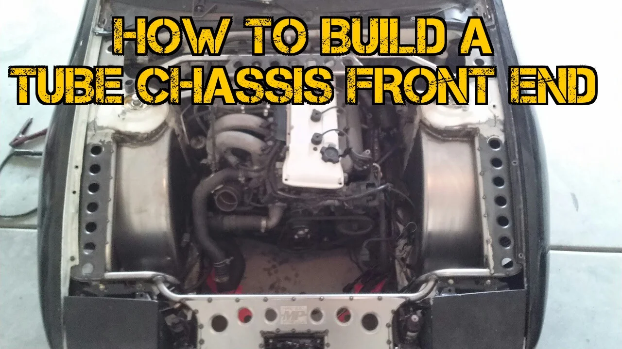
Welcome to the How To Build A Tube Chassis Front End Official Build Blog!.
Welcome to the How To Build A Tube Chassis Front End Official Build Blog! This is the central location of everything you need to know and discuss all videos and talk more about it. Every Wednesday one more video (sometimes two) will be posted until the grand finale where the final uncut videos will be added. Each week, another upload will post here and on all of the social media outlets will alert you. Along the way you will see some build pics, ask some questions, and more!
Make sure you SUBSCRIBE to The Fabricator Series YouTube Channel so you never miss a single episode!
Enjoy!
Chapter One: Strip & Cut
This Chapter covers the basic removal and cutting of components and chassis sheet metal in order to start fabrication. It is extremely important to ensure that the chassis you intend to build is completely straight if the vehicle experienced any type of collision. Be completely HONEST with yourself. If you see any type of frame damage, do NOT modify the chassis.
Chapter Two: Squaring the Front End
This Chapter covers the re-alignment (squaring) the front end fenders and bumper after the factory sheet metal has been cut off and removed.
Once the supporting metal is removed, how do you re-align the fenders and bumper? How do you know that the location is correct for proper body alignment? How many planes have to be correct? The answer is in the video. Squaring the front end is extremely important to ensure all of your body metal and components will fit correctly once you measure and fabricate the new tube structure. If you neglect this step, your entire front end may be out of alignment.
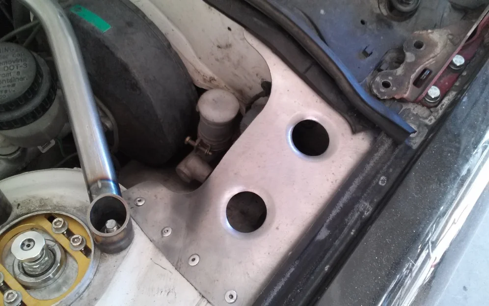
Chapter Three: Mounting Plates
This Chapter covers the design aspects of the front section as well as fabrication and installation of the mounting plates for the primary tubes.
It is very important to remember that most tube chassis front end builds are more "free reign" in the design. As long as you have the essential structural components in place and functioning, the rest of the chassis is pure art. Take as much time as you need to create your design. You can use other builds for inspiration, but ALWAYS create your own design and style.
While contemplating your design, consider things like:
Future Serviceability - The ability to remove components to work on the vehicle is something you should keep in mind as you come up with your design. Some components may be made permanent, but others should be fastened.
Replacing Damaged Tubes in the Event of a Collision - Hopefully you will never have to repair or replace any of your hard work, but do consider the fact that future damage is inevitable. Incorporate a design that will ease future repair and replacement of components.
Ease of Service - Imagine you are building a chassis with a lower support that stretches right past the oil filter. If the permanently mounted tube hinders the ability for the oil filter to come off, you should consider another option. Permanently mounted tubes and designs may interfere with future service. Consider the the time it will take, and the practicality of your design.
Fitment - Fenders, bumper, hood, lights.... They all fit correctly on the factory chassis, so if they are meant to go back on the new chassis, they should fit the same. This particular build will incorporate a Bash Bar into its design, and it is to be completely hidden behind the bumper. That fitment needs to be considered when designing the chassis.
These are just a few things to consider. Most importantly, take your time and let the creative side flow. You don't have any references (like rules for a roll cage) to follow, so make sure you are completely set on your design and stick with it. Take as much time as you need.
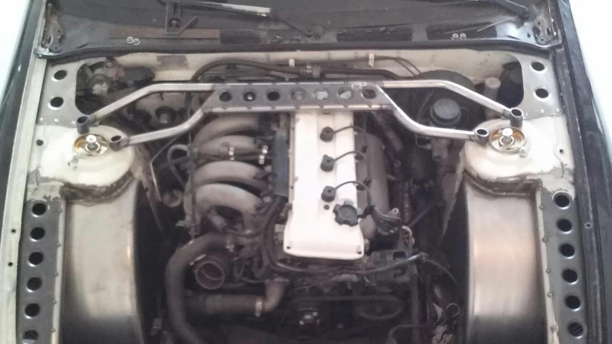
Chapter Four: Fabricating the Primary Tubes
This Chapter covers the design and fabrication techniques of the primary tubes.
This can definitely be tricky to start with. The most important thing to understand is as long as you maintain the correct load and function of the Primary Tubes, the design is entirely up to you.
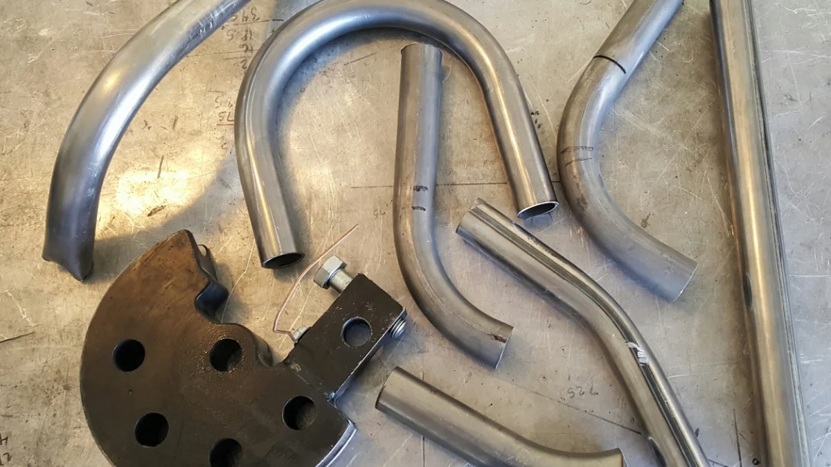
There are dozens of ways to measure and create each of your Primary Tubes, but the method used in this particular chapter comes from using bends found in the cut pile for the purpose of mocking up a Primary Tube design. The best part about using cut pile bends is often finding multiple tubes to use without wasting new material on your build.
Just remember to take your time and really stick with the design you chose, and the rest will come together.
Chapter Five: Installing the Primary Tubes
TAKE YOUR TIME. That is one area that really can't be stressed enough. It is critical that both sides remain even and balanced during installation. Measure as many times as needed to ensure your Primary Tube installation is exactly the same on both sides.
Remember to stick with your intended design. Any changes made to your initial design may change the positioning and functions of your tubes later on down the road. Changes to your build (in a freestyle building sense) often do happen. Be prepared for changes by installing your Primary Tubes with only temporary tack welds. Make sure they are strong enough to hold suring your time of general fab and mock-up, but ensure they can be accessed with a cutting tool so you can make small changes later on down the road if you need to.
Chapter Six: Main Rail End Caps
A short chapter on installing the Main Rail End Caps. Cutting and installing is very simple to do. You can freestyle the installation or use a template method with tape. Either method should net clean a installation.
Chapter Seven: Bash Bar Fabrication
Now we start to really give this build some shape. Fabricating a bash bar is relatively simple, but you must consider the points of contact in your design. The lower section of the bash bar is likely going to be the first point of contact on the car depending on the height of the car. The brackets that mount the bash bar to the chassis should also be a little heavier than the average mild steel. Both the lower bash bar tube and both brackets were upgraded to 0.120" DOM for this build. It will take more abuse before deformation.
Bracket design is also important to the design. There are tons of bash bar designs you can create, but this one is intended to hide nicely behind the factory bumper and serve as the bumper support. Since it takes the general shape of the bumper, the upper and lower bash bar will not be directly above or below one another. The lower bash bar tube will sit more rearward. Load disbursement needs to be considered for both tubes. The lower tube will contact areas from below and push the lower tube more upward while the upper tube will theoretically contact from the front pushing the tube rearward. Your bracket design needs to handle the load accordingly as absorb the load.
Chapter Eight: Front Wheel Tubs
Quite possibly the most anticipated chapter - Front Wheel Tubs. Well, as it turns out, they were added to the build, so leaving the design open to adding front wheel tubs (as discussed in Chapter Three) was a great decision.
There is a tremendous amount of "freestyle" technique involved in this chapter. Just remember to take your time and really work the metal to your liking. There really is not specific method to use. In fact, there are tons of methods one can use to shape and install wheel tubs.
This design did incorporate a full enclosure design by creating outside and bottom walls which help to maintain cleanliness of the engine bay by keeping unwanted dirt and debris out, and maintaining uniformity for aesthetic appeal. Additional structural reinforcement is added by design as the sheet metal joins all points of the previously removed chassis by attaching them into the primary tubes, the new structural support, which were installed earlier.
Chapter Nine: Fabricating the Secondary Tubes
Now we get just a little bit tricky with some compound bending. The Secondary Tubes start at the outer most section of the fender mount and bend around the front then down to the main chassis rail in one shot. The secondary tubes also support the IHeartGussets dimple die panels which were used partially as the fender mount.
Aside from supporting and bracing the fender section, Secondary Tubes also serve as the OEM headlight bucket mounting tab attachment location. The original functioning pop-up headlights will remain on this custom Tube Chassis Front End.
Chapter Ten: Lower Core Support
Kicking off Part 2 of this build is the fabrication of the lower core support. This involves some pretty tricky bending and notching to get everything lined up just right. This particular piece integrates a mounting point for the tension rod brackets just as the OEM lower core support did.
The unique method for creating the mount tabs for the tension rod brackets out of flat steel is one that can be used many times over for similar brackets and mounting tabs.
Chapter Eleven: Upper Radiator Core Support
We had a design change. It was originally planned to run a V-mount setup with a custom built intercooler up top. The owner decided just in time that he was not sure if boost was going to be part of the fina build, and that's ok. Design changes can happen in the build as long as you catch them in time. This particular design up to this point will still permit the installation of the radiator in the OEM location.
The AC was also kept, but a mild design change was implemented to the mounting. In the future, if the build does change to a boosted application, the AC condenser (now V-mounted) can be swapped out for a custom built intercooler which will also maintain the V-mount position. Future planning is very important in a build and was considered during this change.
Chapter Twelve: Radiator Diffuser Part 1
Before this build commenced, it was requested that the front end remain original. No presence of any tyoe of modification should be seen while the hood is closed and the panels attached. It is to be the ultimate sleeper status. So what does that mean for the Tube Front End? The hood latch needs to go back on.
Installing a hood latch to a custom Tube Chassis Front End is obviously possible, but uncommon. The hood is typically secured with hood pins, or some other type of fastener once the tube work is complete. Hood pins are so common that this is the first time I have ever installed a factory hood latch back on a car after building a tube chassis.
So what needed to be done? The hood latch needed to have a factory mounting location, and since the AC condenser was V-mounted, the air would be deflected upward toward the hood as the vehicle moved forward. A radiator diffuser (as they are typically known) is designed to control the air. In this case, the air will be deflected back to the radiator for cooling once the diffuser panel was added.
The general outline and shape can be achieved using a few different methods. The method demonstrated in this video was simply by measuring and contouring to maintain the highest degree of accuracy in the least amount of time.
Chapter Thirteen: Radiator Diffuser Part 2
So we have the diffuser outlined and fitted correctly, but there is now an opportunity to add to the style of it before it is final welded to the chassis. I saw this as a fantastic location for Merrill Performance branding since it will be one of the first things seen as the hood opens up.
The addition of dimple holes to the diffuser actually serve a few functions. First, heat control. At idle, the AC fan will be blowing the air upward toward the diffuser while it dissipates heat. The addition of the dimple holes will allow heat to escape and not soak into the radiator. Second, weight reduction. Yes, we are literally talking about fractions of weight, but at the end of the day - less is less. Finally, style. With the installation of IHeartGussets Gusset Panels all over the chassis, it would be best if the front end would match the rest of it.
The difficult part was maintaining the uniformity of a hand cut hole vs the CNC laser cut holes from IHeartGussets. It only took some precision and attention to detail to make a near perfect match in quality. The result is a functional radiator diffuser that looks absolutely epic!
Chapter Fourteen: Ducting Templates
So far we've seen a few different methods used to match certain shapes and contours with sheet metal. We've seen gauging, measuring, and tracing with both hand-eye coordination and using specific tools. Now we get to another method which involves the use of construction paper to form a template.
Templates are an excellent way to create complex shapes without wasting sheet metal and materials (other than very inexpensive paper). Where there is no way to accurately measure the shape you need to cut out, use a template.
Only ONE Chapter remaining!
Gag Reel
It appears that the Gag Reel is a pretty big hit since many viewers like to have a laugh at some of the funny moments caught on camera during the roll cage filming. I wanted very much to offer the same for this build, but there are over 3 times the amount of videos to sort through and time is running short.
While the Gag Reel is up in the air at the moment, here is one particular moment where I neglected to follow Rule #1 regarding flammable liquids.
More videos coming EVERY WEDNESDAY!
Keep checking back and make sure you SUBSCRIBE to The Fabricator Series YouTube Channel
Ad Free Full Length Videos
Individual chapters will continue to upload as scheduled. If you would like to see the full episode parts from start to finish before the individual chapters get released, you can rent the full episode which will help support future episodes. Your contribution is greatly appreciated.
Part 1: All chapters One thru Eight.
Help fund future episodes of The Fabricator Series with your Donation and receive exclusive SnapChat access! Even the smallest donations go a long way.
Questions? Drop them in the comments below or Email The Fabricator
Likes, Comments, and Shares appreciated by all!


Purge Blocks actually serve more than one purpose. Do you know what they do?